Random Voltage Generator
With the birth of my daughter Leni in September. I began to shift my focus in music from rock and roll and guitars to experimentation and modular synthesizers. This random voltage generator is a product of this shift in focus.
The prototype I built uses a Teensy 2.0. However, you can use most any Arduino or Arduino compatible microcontroller.
Below I’ve included an audio clip, the fully commented source code and a Fritzing sketch of the circuit. The source code can also be found on Github here.
Audio Clip
Here’s a short clip of the random voltage generator in action. I’m running the output into the 1V/Octave Control Input of VCO A of a Make Noise DPO. From there, I’m running the Sine Waveform out into a Make Noise Optomix. The recording was done on a Tascam DP-006 then ran through Logic to bring the gain up around 0 dB.
Source Code
/* Random Voltage Generator * ------------------------ * This sketch reads the values of two (ideally 10K linear) potentiometers * Next, the values are run through the map function to scale the range * and invert the rate. The values are then passed to the random function * that generate values for the analogWrite and delay functions. * * A Fritzing Sketch of this circuit can be found here: * http://jp1971.com/random-voltage-generator/ */ /* Copyright 2014 JP1971 (jameson@jp1971.com) This program is free software; you can redistribute it and/or modify it under the terms of the GNU General Public License as published by the Free Software Foundation; either version 2 of the License, or (at your option) any later version. This program is distributed in the hope that it will be useful, but WITHOUT ANY WARRANTY; without even the implied warranty of MERCHANTABILITY or FITNESS FOR A PARTICULAR PURPOSE. See the GNU General Public License for more details. You should have received a copy of the GNU General Public License along with this program; if not, write to the Free Software Foundation, Inc., 51 Franklin St, Fifth Floor, Boston, MA 02110-1301 USA */ // Define these values as necessary int cvPin = 10; int rangePin = 21; int ratePin = 20; // Leave these values alone int range = 0; int rate = 0; void setup() { pinMode( cvPin, OUTPUT ); Serial.begin(9600); } void loop() { // Read range potentiometer range = analogRead( rangePin ); // Map value to scale appropriate for analogWrite range = map( range, 0, 1023, 0, 255 ); Serial.print( "range: " ); Serial.println( range ); // Read range potentiometer rate = analogRead( ratePin ); // If rate is less than 100, set it to 100. if( rate < 100 ) { rate = 100; } // Use map to invert value rate = map( rate, 100, 1023, 1023, 100 ); Serial.print( "rate: " ); Serial.println( rate ); // Write CV analogWrite( cvPin, random( 0, range ) ); // Wait delay( random( 100, ( rate + 100 ) ) ); } |
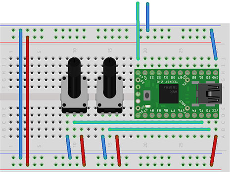
Fritzing Sketch
This sketch assumes that you have a +5V power supply connected to the power and ground rails of the breadboard. The wires running off of the board should connect to the tip (green) and sleeve (blue) of a 3.5mm female jack.
Next Steps
When I get back to working on this project, I’d like to explore modifying the circuit to provide a coltage range of +/- 5V as opposed to 0 to 5V. I’d also like to add jacks to allow for voltage control of the range and rate.